Name Use Cases Using Domain Terminology. All use cases or functionality of the specific system are located inside the rectangle.
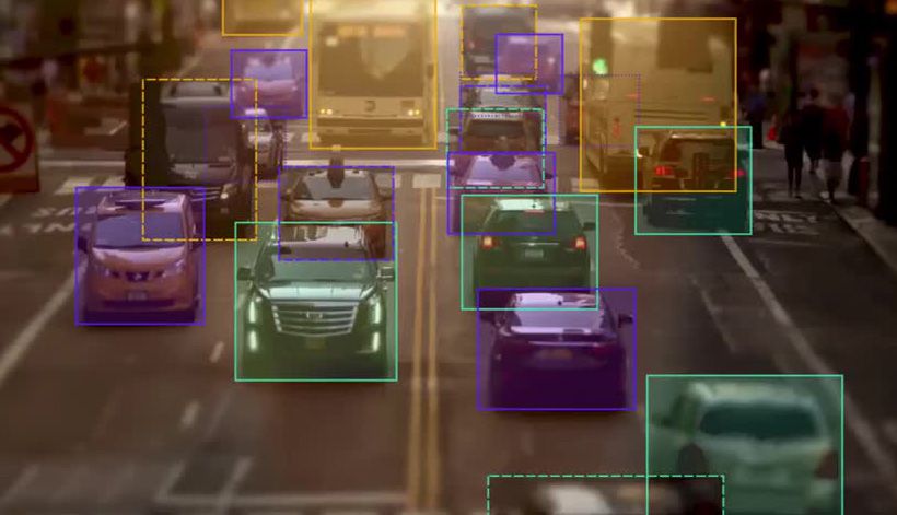
Image Processing Techniques What Are Bounding Boxes
Each oval inside the system boundary box represents a use case.
. Use case diagrams can be used for. The use case diagram shows the interactions of the system with its users and some connections between internal system operations albeit at a high level of abstraction. A Explain the terms actor use-case and system boundary.
Ensure if the alternate workflow in the system is complete. A box that sets a system scope to use cases. The use case diagram shows the interactions of the system with its users and some connections between internal system operations albeit at a high level of abstraction.
We should make sure that each step in the Use Case is testable. A system boundary is a rectangle that you can draw in a use-case diagram to separate the use cases that are internal to a system from the actors that are external to the system. A use case describes a sequence of actions that provide a measurable value to an actor.
A self-scanning system allows a user to scan bar codes of all articles and deduct the sum from the customers shopping account. All use cases outside the. In complex diagrams it is important to know which actors are associated with which use cases.
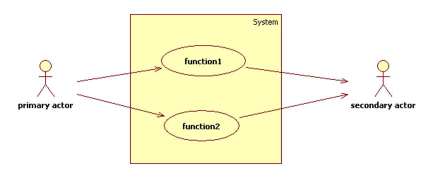
In Figure 2 the arrow from the. The System Domain Box indicates the boundary of the system you want to highlight or focus on. A use case diagram captures the business processes carried out in the system.
Describe the Boundary Box Use Case System Get link. Place Your Primary Use Cases In The Top-Left Corner Of The. Each step explained in the Use Case testing is testable.
The arrows on the use case diagram indicate which actors participate in each use case. In forward engineering use case diagrams are used to make test cases and in reverse engineering use cases are used to prepare the requirement details from the existing application. Draw the use cases on the diagram identify the system boundary place the actors on the diagram and draw the lines connecting the actors to the use cases.
A use case represents a function or an action within the system. Any entity in the relationship map may be used as the system domain. Who are the experts.
A line between actors and use cases. The use case is functional testing of the black box testing used to identify the test cases from the beginning to the end of the system as per the usage of the system. Experts are tested by Chegg as specialists in their subject area.
It does not add semantic value to the model. Each oval inside the system boundary box represents a use case. Notation of System Boundary Subject is a rectangle with Systems name on top of the rectangle.
You can draw a rectangle around the use cases called the system boundary box to indicates the scope of your system. Its drawn as an oval and named with the function. Use Case Diagrams Are Brilliant For Helping With User Experience Ux When Building Apps Business Development Strategy Use Case Software Development Life Cycle.
Indicate Release Scope with a System Boundary Box. Use cases are created when the requirements of a system need to be captured. It represents a functional unit of a large application.
The arrows on the use case diagram indicate which actors participate in each use case. This could be a person organization or an external system and usually drawn like skeleton shown below. Referring to the Shopping Cart Project we can view the relationship map and count the number of entities that are in the scope of the project.
Use Case Names Begin With a Strong Verb. In this example there are 7 entities. Alternatively a use case can be thought of as a goal that some actor can achieve with the system.
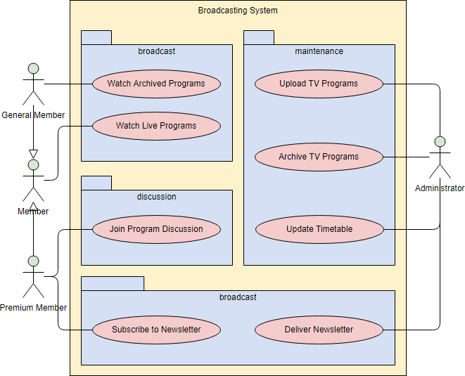
Other Apps - April 17 2022. Anything within the box represents functionality that is in scope and anything outside the box is not. System Boundary Boxes The rectangle around the use cases is called the system boundary box and as the name suggests it indicates the scope of your system the use cases inside the rectangle represent the functionality that you intend to implement.
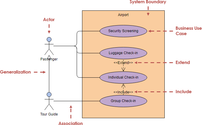
Actor in a use case diagram is any entity that performs a role in one given system. B Describe 4 use-cases and draw a use-case diagram of a self-scanning system in a shop. An actor association is an arrow connecting an actor to a use case.
This arrow represents a conversation between the actor and the system component responsible for executing the use case. Based on the knowledge of the system or even domain we can find out the missing steps in the workflow. A use case is drawn as a horizontal ellipse on a UML use case diagram as you see in Figure 1.
Identify the system boundary draw the use cases on the diagram place the actors on. Specifying relationships in diagrams. When drawing the use-case diagram an analyst should do the steps in this order.
A use case diagram is quite simple in nature and depicts two types of elements. Model the context of a system. Normally domain experts and business analysts should be involved in writing use cases.
A use case represents a function that the system performs. Avoid Meaningless System Boundary Boxes. Describe how a use case interaction between user and system can be used to identify Entity Boundary and Controller classes in our design.
We review their content and use your feedback to keep the quality high. A system boundary is an optional visual aid in the diagram. One representing the.
Requirement analysis and high level design. The actors accessing the system are placed outside the system boundary. By using this technique the test team creates a test scenario that can exercise the entire software based on the functionality of each function from start to end.
Use Case Diagram Tutorial
Use Case Diagram Tutorial

What Is A Use Case How To Write One Wrike
Identifying Use Cases


0 Comments